- PCB Blog
- Future Trends of Flexible Circuit Boards
- Rigid-Flex PCB Stack-up for Impedance Controlled Designs
- Control Impedance Between Rigid PCB and Flex PCB
- Flex PCB Reliability and Bendability
- Normal Flex PCB Specifications
- Flex PCB Polyimide Coverlay and Solder Mask
- Flex PCB Boards and Connectors
- About RA Copper and ED Copper
- Introduction of Flexible PCB
- 5 Tips For Designing Flexible PCB
- Advantages of FPC (Flexible PCB)
- Evolution of the Flex Printed Circuit Board
- Benefits of Using Flex Circuit Boards
- Why Rigid-Flex PCBs are Economical?
- Flexible PCB vs Rigid PCB
- Development of Flexible printed circuit board (FPC) market
- Traditional Manufacture Engineering of FPC Substrate
- Development Trend of FPC Board
- Flex PCB and the Manufacturing
- About Flex PCB design
- About Flex PCB and Assembly
- How to Ensure Flex PCB Design Success
- How to Select the Appropriate FPC Materials?
- The Differences In Rigid PCB, Flex PCB and Rigid-Flex PCB
- Flex-Rigid PCB Design Guidelines
- Beneficials for Polyimide Flex PCB Boards
- About Stiffener on Flex PCB FPC circuit Boards
- About ENIG and ENEPIG
- PCB Surface Finish Comparison
- Copper Thickness for FPC Boards
- Interconnect Solutions for Flexible Printed Circuits and Etched Foil Heaters
- Advantages and Disadvantages of Rigid-Flex PCB
- About FPC Plating Process
- About EMI shield design for Flex Printed Circuit Board
- PCB Assembly Blog
ABOUT FLEX CIRCUIT STIFFENERS
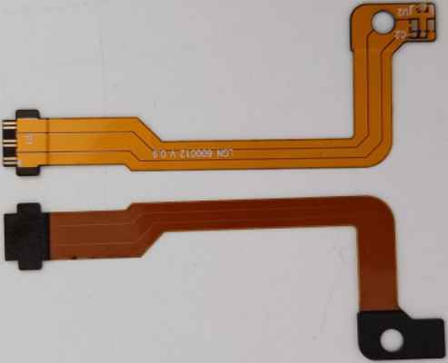
When it comes to flex circuits and rigid-flex PCBs, stiffeners are a common and important requirement in many designs as they improve the durability and reliability of the flex circuit in many applications.
Stiffeners also provide a mechanical function for the flexible area and are not part of the electrical requirements of the overall part. If your board requires stiffeners on one or both sides of the flex, it may require multiple lamination cycles, which will add to the cost and the lead time. However, there are certain cases where stiffeners are ultimately required.
Flexible PCB Stiffener Requirements
Flexible PCB stiffener requirements fall under the following usage categories:
1. Rigidizing connector areas for stress relief of larger connectors or repeated insertions of the connector.
2. ZIF (Zero Insertion Force) Thickness Requirements.
3. Localized Bend Constraint(s).
4. Creating a flat surface for the placement of SMT pads and components.
5. Minimizing component stress Managing heat dissipation (aluminum and steel).
6. Make the array rigid enough to run through the automated assembly processes without a fixture
Things to Know About Flex PCB Stiffeners
Stiffeners are added to the flexible circuit as one of the final fabrication steps and can be applied with either a layer of pressure sensitive adhesive (PSA) or a layer of thermal set adhesive. From a low-cost perspective, the pressure-sensitive adhesive application will most often be slightly less expensive. Thermal set on-flow adhesive (traditional PCB prepreg) requires the flex PCB to be placed back in the lamination press to apply the heat and pressure needed to cure the adhesive, which has to be pre-cut to the specific shape of the stiffener itself.
Make sure when specifying PCB stiffeners to go along with plated-through hole components that the design will have the stiffener on the same side of the board where you’re inserting the component, so you can access the solder pads. In these applications, being able to accurately register the holes on the stiffener to the plated through holes on the PCB is critical to ensure that the component leads can be easily fed through the holes. As part of this process, customers need to work with their flex PCB fabricator in order to ensure that the adhesive system used, and the method of registration used will be adequate to accomplish the customer objectives.
Adding stiffeners to flexible and rigid-flex PCBs will add extra processing time, material, and labor, which will add cost. As a design tip, stiffener and coverlay termination points on top and bottom layers should overlap a minimum of 0.030" to avoid stress points and keeping all the stiffeners the same thickness reduces processing time in fabrication.
When choosing the thickness of the stiffener material for flex and rigid-flex PCBs the best method for reducing cost and lead time is to stick to the most common laminate thickness such as 0.010", 0.031", 0.047", or 0.062", just to name a few. Each fabricator has its own stock of different products, so it is important that you work with them to determine what the best common thickness is to ensure that you are not specifying a thickness that creates cost and logistics challenges.
Why Use Stiffeners in Flex Circuit Application
Flexible PCB stiffener requirements fall in the following usage categories:
A1. Rigidizing Component / Connector areas
B2. ZIF (Zero Insertion Force) Thickness Requirements
C3. Localized Bend Constraint(s)
A1. Rigidizing Component / Connector Stiffeners
Function:
1. Creates a localized rigid area where components / connectors are attached.
2. Protects solder joints by preventing bending of the flex in component area.
Material Options:
. FR4, Polyimide, Aluminum, Stainless Steel
. Variety of thicknesses available
. Attachment methods: Thermally bonded with flex adhesive, or pressure Sensitive Adhesive (PSA)
B2. ZIF Stiffeners/Golden Finger Stiffiners
Function:
Localized thickness increase at contact fingers to meet specific ZIF connector specifications.
Material Options:
. Polyimide Only
. Variety of thicknesses available to meet specific design requirements
. Attachment methods: Thermally Bonded with flex adhesive only
C3. Localized Bend Constraints
Function:
Restrict bend area(s) to specific location(s) in a flex design to either facilitate final assembly, achieve specific bend requirement(s) or other end use requirement.
Material Options:
. FR4, Polyimide, Aluminum, Stainless Steel
. Variety of thicknesses available
. Attachment methods: Thermally Bonded with flex adhesive, or pressure Sensitive Adhesive (PSA)
