- PCB Blog
- Future Trends of Flexible Circuit Boards
- Rigid-Flex PCB Stack-up for Impedance Controlled Designs
- Control Impedance Between Rigid PCB and Flex PCB
- Flex PCB Reliability and Bendability
- Normal Flex PCB Specifications
- Flex PCB Polyimide Coverlay and Solder Mask
- Flex PCB Boards and Connectors
- About RA Copper and ED Copper
- Introduction of Flexible PCB
- 5 Tips For Designing Flexible PCB
- Advantages of FPC (Flexible PCB)
- Evolution of the Flex Printed Circuit Board
- Benefits of Using Flex Circuit Boards
- Why Rigid-Flex PCBs are Economical?
- Flexible PCB vs Rigid PCB
- Development of Flexible printed circuit board (FPC) market
- Traditional Manufacture Engineering of FPC Substrate
- Development Trend of FPC Board
- Flex PCB and the Manufacturing
- About Flex PCB design
- About Flex PCB and Assembly
- How to Ensure Flex PCB Design Success
- How to Select the Appropriate FPC Materials?
- The Differences In Rigid PCB, Flex PCB and Rigid-Flex PCB
- Flex-Rigid PCB Design Guidelines
- Beneficials for Polyimide Flex PCB Boards
- About Stiffener on Flex PCB FPC circuit Boards
- About ENIG and ENEPIG
- PCB Surface Finish Comparison
- Copper Thickness for FPC Boards
- Interconnect Solutions for Flexible Printed Circuits and Etched Foil Heaters
- Advantages and Disadvantages of Rigid-Flex PCB
- About FPC Plating Process
- About EMI shield design for Flex Printed Circuit Board
- PCB Assembly Blog

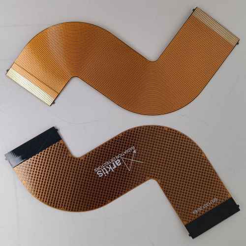
Flexible circuits offer compact, low-mass packaging that can reduce space and weight by some 75%. While flexible circuits have been around for years, the clamor from medical-device manufacturers for smaller and lighter applications are bringing flexible circuits to the forefront as a viable way to meet the demands.
Limited knowledge of flexible circuitry means engineers are only just beginning to learn ways that flexible circuits can be used in their designs. Here are five tips for designing with flexible circuits.
1. Learn how flexible circuits work
Knowing the types of flexible circuits and their capabilities and applications, will provide guidelines for designing with them. Knowing what doesn't work can be just as important. When possible, contact a reputable flex-circuit manufacturer for guidance on material properties and limitations.
2. Build a flex circuit mock-up
The best way to determine the viability of a design is to create a physical flex circuit mock-up. This involves first determining the system points to be electrically connected via flex circuitry and a termination method such as mating connectors, pins, or ZIF. Next, determine an approximate circuit “footprint” that will provide conductor routing to each termination location. Review the schematic or net-list details along with special electrical requirements, such as plane layers, to determine an approximate layer count. Examine sample circuits of similar layer counts to see if the proposed design will provide sufficient flexibility. If no sample circuits are available, you might get free samples from a flex-circuit manufacturer.
Then review the mechanical requirements to ensure that bend radius fall within acceptable values for circuit thickness and layer count. Refer to IPC-2223 for guidelines on acceptable bend radii. Construct a “paper doll” outline of your flex circuit using heavy paper and use it to check for fit. Make modifications as necessary. Continue constructing paper prototypes and make modifications until the fit works. Lastly use 0.010-in. (0.25 mm) polyester film to reconstruct the prototype to make a representative mockup. Install it in a prototype housing and make dimensional adjustments as necessary.
3. Get a mechanical sample
Before investing a lot of time and money creating a functional flex-circuit prototype, test a mechanical sample to ensure the flex circuit has the right form and fit. Form refers to the physical size, shape, and mass of the part, while fit refers to its environmental interfaces. A mechanical sample helps avoid installation problems or latent mechanical issues that could cause failures.
4. Minimize circuit costs
The big cost drivers for flexible circuitry are the overall circuit size, number of layers, and feature size. Line widths and spaces, pad sizes and small hole sizes cost more. Follow recommended tolerances wherever possible and design unbonded areas only where they are absolutely necessary. If there are no SMT components, or they are on only one side, consider using a stiffened flex in lieu of a rigid flex. Stiffeners can be far less expensive than a rigid-flex circuit. And use standard materials whenever possible.
5. Don't ignore the minimum bend radius
Several problems arise when bending a circuit too sharply. Compression on the inside radius can cause wrinkles in the cover coat. Stretching on the outside bend can tear the cover material and break conductors. Start the mechanical design by establishing the bend radius. If the radius is at least ten times the material thickness, there is a good chance the circuit will function reliably. To improve reliability, reduce the overall thickness in the flex area so it withstands flexing.
Feel free to contact us for further enquiries for your flex PCB project.